
Welcome to the unofficial page of the...
![]() Mk
I
Mk
I
What they're saying about the SMLI:
"Now you've
all got me really frothing at the mouth" -
GTAV6
"I
don't want
a crappy 8,000 rpm" - Owen
"Kudos has
been allocated... I'm almost
dying of excitement!" - HCB
"OMG
OMG OMG! FUCKING AWESOME! FUCKING FUCKING FUCKING awesome!"
- HCB
"I thought my
rheobus was pretty |33t but this makes it look like simple addition compared
with calculus!" - Cyclonite
"What does crack me up is the excitement generated by an analogue gauge in a digital age.." - HCB
"This
one is VASTLY superior. I've had it running virtually non-stop.
I've done every stupid thing i can think of to its settings, I've
run as many other apps as i possibly can and I can't unsettle it. no crashes, no
conflicts. So far, it's perfect." - GTAV6
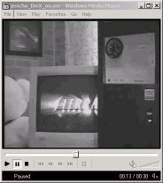
DivX;) Tachometer movie at http://www.OwentheGreat.com, 1.03 Mb
The Atomic Tech thread for the mod: http://www.atomicmpc.com.au/forums.asp?s=2&c=9&t=2
Yarrago's SMLI Host Application 1.0
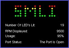
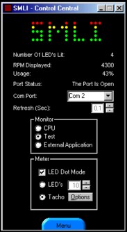
The host software which interfaces with the SMLI interface board
Note: Yarrago's Domain may be offline for up to a couple of weeks around the start of January 2002
Visual Basic 6 Runtimes @ Microsoft.com
Users who have not used a Visual Basic
application before will need to download and install this package.
SDK for the SMLI Host Program @ Yarrago's Domain
If you have artistic skills or programming knowledge you might want to download
the SDK so that you can get the most out of the SMLI host software.
-------------------------------------------------------------------------------------------
The source code files for the PIC Microcontroller are not online currently, as the micro-controller code is always being tweaked, or feature creeped. Contact Goth on the atomic forums if you are looking for the Hex or Assembler files.
--------------------------------------------------------------------------------------------
Bill of Materials and technical description based in part on the SMLI page @ OwenTheGreat.com, partially copyright Ó 2002 OwenTheGreat
| Parts List - Serial Microcontroller LED Interface / CPU Utilisation Tachometer | |||||
| Adapted from http://www.owenthegreat.com/computer/othermods/cpuloadledmeter/smli/, some revisions. | |||||
| Name | Qty |
DSE |
Jaycar |
||
| PIC16F84 Micro controller | 1 | Z9175 | $9.95 | ZZ-8500 | $11.95 |
| 18 pin DIL Socket | 1 | P4180 | $0.41 | PI-6503 | $0.35 |
| 74LS138 3 of 8 Decoder | 1 | Z5284 | $1.50 | ZZ-5138 | $1.50 |
| 16 pin DIL Socket | 1 | P4160 | $0.37 | PI-6502 | $0.34 |
| BC557 PNP Transistor | 8 | Z1340 | $0.30 | ZT-2164 | $0.26 |
| BC547 NPN Transistor | 1 | Z1300 | $0.30 | ZT-2152 | $0.20 |
| 1N4148 diode | 1 | Z3120 | $0.06 | ZZ-1100 (5) | $0.32 |
| 4.7 k Ohm resistor | 12 | R1090 | $0.04 | RR-0588 (8) | $0.38 |
| 22 pF ceramic capacitor | 2 | R2243 | $0.10 | RC-5316 (2) | $0.28 |
| 4 MHz crystal | 1 | Z9900 | $3.95 | RQ-5274 | $3.95 |
| 120 Ohm resistor | 6 | R1052 | $0.04 | RR-0550 (8) | $0.38 |
| Proto-type board | 1 | H5603 | $2.80 | HP-9550 | $3.70 |
| Standard 3mm LED's | - | Z40-- | $0.27 | ZD-17-- | $0.25 |
| Standard 5mm LED's | - | Z40-- | $0.32 | ZD-17-- | $0.33 |
| D9 Female connector | |||||
| 1 | P2685 | $1.35 | |||
| PS-0804 | $1.20 | ||||
| 1 | P2686 | $2.20 | |||
| D9 plastic Backshell | PM-0808 | $1.80 | |||
| LED Type | Resistor Value |
| Regular Red | 120 W |
| Regular Orange | 120 W |
| Hi-Intensity Red | 120 W |
| High-Intensity waterclear green | 120 W |
| Jaycar ZD-1778 waterclear yellow or similar | 120 W |
| Infra-Red (Just the thing for those of us with Predator vision) | 120 W |
| Jaycar ZD-1795 waterclear yellow or similar | 100 W |
| Regular Green | 100 W |
| Regular Yellow | 100 W |
| High-Intensity Blue | 68 or 56 W |
| High-Intensity White | 68 or 56 W |
| Ultra High-Intensity green eg. Jaycar ZD-1779, 7Cd or greater | 68 or 56 W |
| Waterclear Ultra-Violet | 47 W |
PCB's and Schematics


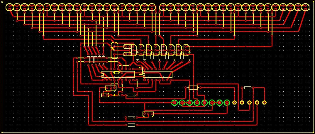
SMLI Main LED Array Tachometer Drive
(Note that Demo Mode is disabled by pulling pin 10 on the PIC to ground, this is shown on the PCB
below but not implemented on the schematic)
Original PCB layout by OwenTheGreat


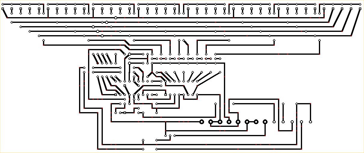
PCB component side layout PCB Tracks (Positive suitable for etching)
Original Schematics and PCB @ Owenthegreat.com, Copyright Ó 2002 OwenTheGreat

31 * 3.6 cm
The second version has the LED's right up against each other, with only 1 row of holes between each set of leads, when built on protoboard. You need to partially file off the small flange at the base of the LED's to make them fit together like this, but it uses less board area than the above design
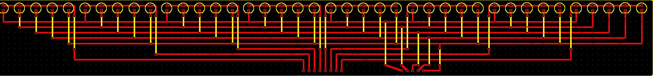
A new 40-LED driver board with ICSP support (Theoretically.... If you build it, Email me!)

A Demo Mode jumper is between the IC's, and the jumper below the PIC is for in-circuit programming, leave it out normally.
The extra transistor is an NPN device, and the diode under the chip is a 1N4148, see the ICSP schematic for more info.
Off-Board connections from L to R, with column connections at the top:
These connections are 0.2'' apart to accommodate PCB mount terminal blocks
1. 12v (Use a passthrough Molex connector for the power rails!)
2. Gnd
3. Gnd.
4. 5v
5. Tacho Gnd.
6. Tacho 12v
7. Tacho Backlight (12v)
8. Tacho Signal
9-11: Serial port pins 3,4,5 (Pin numbering for 9-pin RS-232 port)
12-13 Serial port pins 7,8
And 40 LED's, with the drive hardware on the same board - These LED's have plenty of space in between, as with my first LED board

And a version with the LED's close together
USB 1.1 version (Uses FTDI FT232BM USB UART IC) by CrazyOldGuy

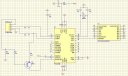
JPG format Protel Schematic file
FTDI
chip Datasheet @ Future Technology Devices
International Website![]()

In-Circuit Serial Programmer Schematic (UNTESTED) by g0th.
As it turns out, it is not necessary, as previously believed, to wire the port in an 'always ready' configuration, similar to a null modem.
This should allow us to use some of these pins to program the micro in circuit, with any JDM-Programmer compatible software.
Fine Print 1.0
This site is the intellectual property of Luke Weston, aka g0th. Copyright 2002-3
Original schematics and source code copyright (2002) Owen Hedger aka OwenTheGreat.
SMLI Host Application by Yarrago, don't pinch it.
p = 3.14159265358979323846264338327950288419716939937510582097494459230781640628620899862803482534211706798214808651328230664709384460955058223172535940812848111745028410270193852110555964462294895493038196442881097566